
Figure 1
To know roll forming, you need to know the industry jargon, so that everyone speaks the same language.
Editor’s Note: This article is based on “Roll Forming Tooling Setup and Troubleshooting,” a presentation given by Steve Ebel at FABTECH, Nov. 6-9, 2017, in Chicago, www.fabtechexpo.com.
An operator sets up a roll form line, runs a test part, and finds the result out of tolerance. So he tweaks the line and runs another test part, measures it, then tweaks the line again. And again. And again.
Roll forming is a complex process, but setting up a line doesn’t have to be so arduous. Why does setup take so long? Operators and supervisors can blame old equipment or unrealistic tolerance requirements.
Or material can be a major issue. A strip can have camber or a curvature. Camber can be imparted on material during the rolling or slitting process, as well as in upstream processes in your shop. Mill coils with edge wave that are slit into narrower coils show random camber in the outer stands, affectionately known as “snakes.” You also have crossbow, dishing, center buckle, or oil canning. Good leveling can help minimize these material problems.
In other words, material matters and purchasing practices need to be part of the conversation when looking to improve the consistency of any roll forming operation. But you can’t ignore best roll forming practices either.
Many challenges can be traced to poor documentation of best practices, insufficient machine and tooling maintenance, and a lack of training. In truth, setting up a roll forming machine really shouldn’t be a black art.
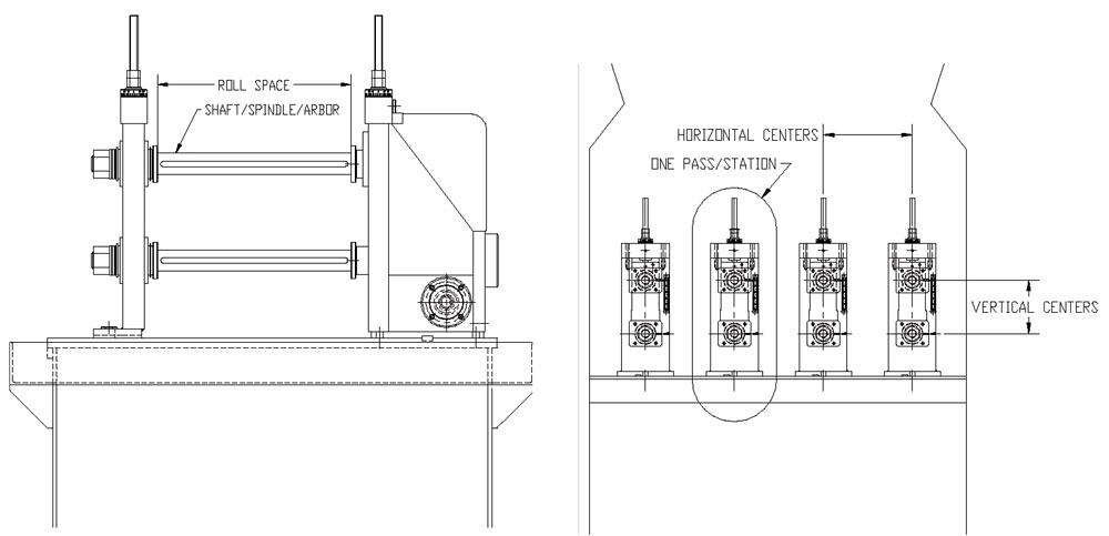
Before diving into the specifics, operators, supervisors, and maintenance technicians all need to speak the same language (see Figure 1). If someone mentions a roll forming machine’s shaft, spindle, or arbor, that person is referring to the point on the roll former where the roll tooling is inserted.
Measure from one side of the shaft (or spindle or arbor) to the other, and you have the roll space. Specifically, the roll space is the area between the hub on the shaft, connected to the inboard (or drive) housing, and the outboard stand. At the end of the shafts, flush against the inboard housing and outboard stands, are the machine face alignment spacers, also called the spindle hubs.
Measure from the bottom shaft’s centerline to the top shaft’s centerline, and you determine the vertical centers, also called the vertical distance. The roll former reaches its full vertical range when the upper shaft is adjusted all the way up and the lower shaft is adjusted all the way down. Measure from the base to the bottom shaft’s centerline, and you get the base-to-centerline distance. And if you measure from the bottom shaft’s centerline in one station to the bottom shaft’s centerline on the next station, you determine what’s known as the horizontal centers.
And what’s a station? It’s the structure holding one toolset, held in place by the upper and lower shafts. It’s also called a roll stand, or one pass in the roll forming process. Each stand has a set of two rolls with spacers that align the roll horizontally along the shaft. The space between the rollers, usually set at the material thickness being processed, is the roll tooling gap.

Figure 2
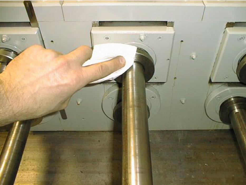
Before inserting new tools, be sure to clean the machine face alignment spacers.
If operators set up a roll forming machine incorrectly or spend too much time on the task, they may be struggling to find the right tools. Any efficient roll forming operation needs to label and organize the tools and spacers in a logical fashion, ideally near the point of operation. Operators with a basic understanding of roll forming should be able to read the setup sheet and find the tools they need without asking anyone.
Before inserting the tools, clean the shafts and machine face alignment spacers, the ones closest to the roll stands (see Figure 2). This sets the foundation for a good setup and predictable and repeatable machine operation.
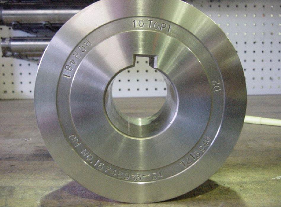
Per the setup sheet, determine the location for the first pass and insert the tools for the first pass onto the machine: specifically, a spacer followed by a roll, followed by another spacer. When installing the first pass, always make sure the stamped ring (with the roll number and other information) is facing you, and the numbers are in the proper sequence for the job (see Figure 3).
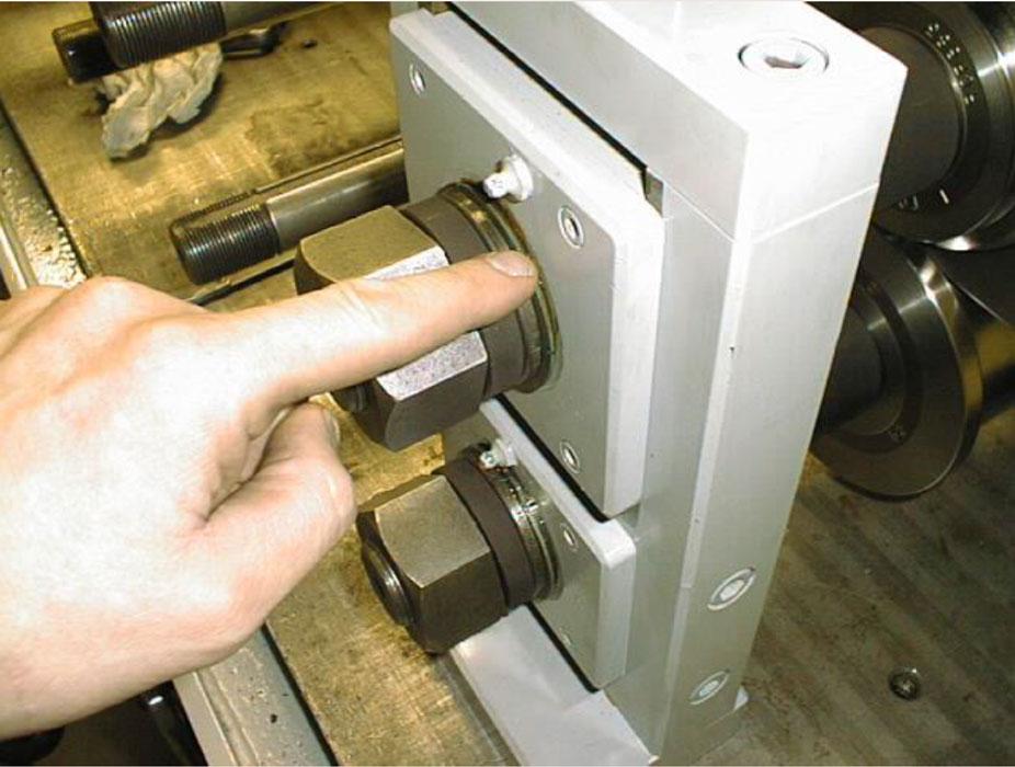
Once the first station tools are in place, put the outboard stand onto the spindles and install and tighten the shaft locking nuts. Check the inner race of the nut assembly to ensure it does not rotate or otherwise run against the outboard stand (see Figure 4). If the race is loose, tighten the nut more to ensure all is secure. Next, lock down the outboard stand with hold-down screws or clamps (see Figure 5).
With the tools in place, retrieve the material to be roll formed and measure its actual thickness. A strip can be labeled “16 gauge,” for example, but this doesn’t necessarily mean the material is exactly 0.060 inch. Every gauge has a range, and the actual material may be a little thicker or thinner.
With the material thickness known, use a feeler gauge on both the tool’s inboard and outboard sides to preset the roll tooling gap, adjusting the vertical distance between the upper and lower shafts (see Figure 6). The pre-gap procedure—determining the gap before the material is in the rolls—checks for clearance. You never want to attempt to run 0.060-in. material through a 0.030-in. roll gap.
You can establish a baseline setup chart by recording the gap between the top and bottom roll flange on both the inboard and outboard side for each pass of roll form tooling.
Once everything is set, you can run the material into the roll pass, then reset the rolls as needed. The roll gap on older roll formers typically is a little loose. Once the material is introduced to the rolls, the material naturally pushes the top rolls away from the bottom rolls, changing the roll gap. This is why you need to re-gap the rolls once the material is in the machine.
All of this should be documented in the setup sheet. But proper documentation is only half the battle. The other half involves maintaining the machine and making sure everything is in proper alignment.
For example, the roll stand adjustment screws, which allow you to change the vertical centers, require routine maintenance (see Figure 7). The nut and screw should be free of debris and in good working order. Turning the screw should move the vertical centers by the specified amount.

Figure 3
When you install tools on the first roll station, make sure the stamp ring is facing you and the numbers are in the proper sequence.
Defining the Problem
When a part emerges from the roll former outside of specifications, you need to isolate and define the problem. Only then can you take appropriate measures to fix it.
A good straight edge is your friend. Use it to check the mill face and machine face alignment to see how accurately the roll former is aligned, station to station and top to bottom (see Figure 8). If something doesn’t line up, you’re on your way to isolating the problem.
If you cannot isolate the problem, inspect the strip as it emerges from each pass to ensure that pass is doing what it is designed to do. If a flange isn’t where it’s supposed to be after a specific pass, something’s amiss.
Once you isolate the problem, you can run the strip to the station (or stations) in question and then back the roll former up a few inches (see Figure 9). Look for pressure marks, alignment issues, or if the roll stops are being hit too hard.
Roll stops are designed into the roll tooling to control the strip edge, so the strip will not wander. The roll designer designs to the maximum material condition, not only on the thickness but also on the strip width. So if the strip is over the maximum on the width, the rolls cannot accommodate it, which of course creates problems.
If you find that the problem is isolated to a particular pass, cut the workpiece material on either side of the pass, raise the roll tooling up, remove the material, and inspect the piece for problems.
You also can use a mirror and flashlight to help isolate the problem, looking to ensure you have the proper gap and that the tooling is touching the material as it should (see Figure 10). Look at the roll’s dimensions to ensure it matches what’s called for in the tooling design documents.
When you can’t check the roll tool faces with a straight edge, you can use this trick to check if the roll tools are aligned properly: Smear grease or heavy oil in a straight line across the width of the workpiece and run the strip through the tools (see Figure 11). The grease pattern that shows up on the rolls tells you where the tools are touching the material.
A repeatable roll forming operation is an aligned one. All components—the machine face, the shafts, the spacers, and rollers—need to be aligned. A misaligned machine changes the space of the roll gap, which in turn can change the product shape.

Figure 4
After tightening the nut on the outboard stand, make sure the inner race is snug and cannot be rotated.
The product may still be within tolerance, but the truth is that the machine isn’t operating as it was designed. If you see excessive wear on just one or two pairs of rolls, the tools aren’t lining up the way they should—which goes back to alignment.
Check for the easiest problem to solve first: loose shafts. Remove all of the roll tooling and outboard stands. Check the shafts and then tighten as needed. Next, place all the outboard stands back on the machine spindles and then slide them into their appropriate position. Once the stands are in place, use a gauge to ensure the top and bottom shafts are parallel to each other (see Figure 12).
After this, make sure the bottom shafts are aligned (see Figure 13). Use a long straight edge on the bottom spindles and push the straight edge up against the machine face alignment spacer or spindle hub. Keep the tolerance on the alignment of the bottom shaft’s alignment hub must be kept to within 0.005 in. from the first station to the final station.
You check the alignment of the top and bottom shafts of each stand in the same way, though usually with a shorter straight edge. Keep the tolerance on the alignment from the bottom shaft alignment hub to the top shaft alignment hub within 0.002 in.
If you can’t keep those tolerances, you’ll need to correct the machine face alignment—one of the most overlooked and neglected components of roll form machine maintenance (see Figure 14). To align the machine face, you either can grind the machine face alignment spacer or shim the bearing sets in the gearbox.
Troubleshooting in roll forming is less like a path and more like a web. Many symptoms may not have just one cause. Figure 15 gives you a taste of the possibilities—just a few causes of some of the common symptoms in roll forming.
You need to make sure all the web strands are healthy, from machine alignment and tooling to material quality.
Leave no strand untouched, and you’ll find that roll forming machine setup is a lot easier, much more repeatable and predictable, and less of a mystery.